During my time at KSU Motorsports Formula SAE I had the role of the design lead and handled 3 major projects, apart from the manufacturing of the car itself. These design projects consisted of an intake for the engine, the differential carriers, and the chassis.
The intake:
The goal of redesigning this intake from the prior intake was to increase the amount of air getting to the engine, equalize the air flow throughout the runners, work with exhaust design to maximize hp and torque, and shift the power band of the yamaha r6 engine towards max power at 10,000 rpm.
The overall geometry of the intake was improved so that the air flowed from the side inlet into the plenum and down the runners. The prior intake design sacrificed air flow for packaging and had the runners running from the top of the intake curled back to the inlet port on the engine. It also was positioned with its plenum hovering extremely close to the engine, causing the plenum to heat up and constantly heat soak the air. This fundamentally was heating the air in the plenum and feeding the engine the hottest air and re positioning this out of the way and with more laminar flow were goals that I had set for this intake.
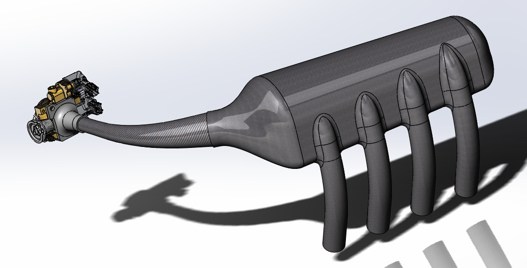
The intake I ended up concluded on was a 3.8L plenum that would have 7.8 inch runners all paired to a side inlet pipe for the air redirection. I calculated 3.8 L for the plenum size based off the 20mm air resistor, single throttle body, and bore size vs the stock Individual throttle bodies, boresize, and no restrictor. The results for the runners were based of real world testing on the same motor on a dyno with a test intake and multiple runner length tests.
Here is the intake that I ended up with! This was constructed out of prepreg carbon fiber and its plenum and runners were made as a single part by using 3D printing to help aid manufacturing. 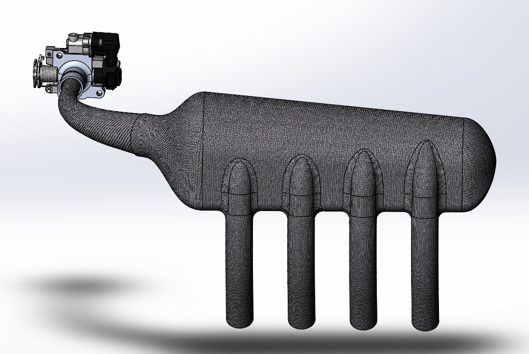
Adjustable Differential Carriers
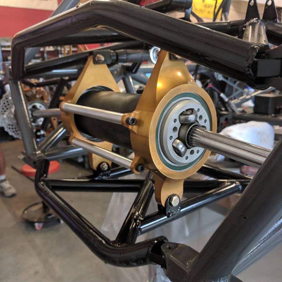
The Diff Carriers design goal was to eliminate the need for an idle chain tensioner sprocket. This was due to its inconsistency in tensioning and constant issues/maintenance, it was also redesigned to stop the bearings from moving out of the hubs. The bearings in the diffs are held in with a press fit so a lip was added on the end of the carriers to stop the bearings from coming outwards. The bottom of the carrier was pinned and the top was attached to a turnbuckle, the turnbuckle would then be tightened to need and would be something that would not require the car to be off the track for too long if need tightening. This carrier was made out of aluminum 60601 T-6 and had a factor of safety of 3.4. The factor of safety was left high due to the last pair of diff carriers failing on the dyno. It was later discovered that this was due to incorrect FEA.
Here is the part, check it out!
The Chassis
The goals of the chassis:
- Reduce the total weight of the entire chassis from 78-lb to 69-lb,
- Increase cockpit area for ergonomics
- Provide proper triangulation for the bell cranks and suspension points
- Maintain the theoretical torsional stiffness of the prior frame
These specifications were provided to me after the old frame was torn down and weighed . In order for me to redesign the new chassis it was important to me to analyze the prior design to see what problems need to be addressed and why a brand new geometry was required. After conducting my analysis, I found that from a design engineering perspective that I did not have enough quantifiable data to justify a new frame geometry for the car. The prior geometry had been now used for 2 years and although the team did not have any data regarding its real-life torsional stiffness, the frame geometry as a whole did not fail throughout the season. Due to this, I decided to address the goals that had been set and keep the concept of the prior geometry. I also had to adjust the geometry to match the new kinematic skeleton provided by the vehicle dynamics.
What I changed:
- Cockpit Ergonomics
- Front Bulkhead load geometry
- Bell crank and suspension triangulation
- Shortened the rear box
- Engine position relative to main roll hoop
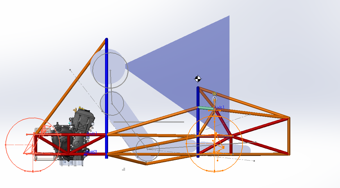
I used Solidworks weldments, 3D Sketching, and top-down design technique to model my frame.
This frame was designed to adhere to the rules that can be found at the link below and is constructed of 4130 Chromoly Steel.
After setting up the initial skeleton of the design based off the knowledge I had gained from chassis design books, prior alumni frame designers, online forums, FSAE Chassis judges, and other peers, I moved to simulating the torsional rigidity of the frame since this was one of the key metrics to affect the vehicle dynamics of the vehicle.
Since the new frame had been made larger and more lightweight, I expected the end results to show a decrease in torsional rigidity.
I tested this by applying a 100 N moment around the front control arms where the hub would be mounted. I then pinned the rear box of the chassis to simulate the moment the vehicle direction changes since this is where maximum twisting force would be. I then modified my chassis design to address the weak points found from my simulation and continued iterating on the design until I had felt comfortable with the final results in the time allocation I had.
The final torsional rigidity value of this design resulted in a 0.53mm displacement from the 100N moment.
The final parameters for this design can be found below:
Assembly = 342.927 pounds
Volume = 5822.266 cubic inches
Surface area = 14541.639 square inches
Center of mass: ( inches )
X = 0.404
Y = 13.363
Z = 0.273
Principal axes of inertia and principal moments of inertia: ( pounds * square inches )
Taken at the center of mass.
Ix = ( 0.999, -0.044, 0.008) Px = 29303.168
Iy = ( 0.044, 0.998, 0.038) Py = 126249.177
Iz = (-0.010, -0.038, 0.999) Pz = 138524.806
Moments of inertia: ( pounds * square inches )
Taken at the center of mass and aligned with the output coordinate system.
Lxx = 29499.998 Lxy = -4286.358 Lxz = 891.908
Lyx = -4286.358 Lyy = 126077.374 Lyz = 431.523
Lzx = 891.908 Lzy = 431.523 Lzz = 138499.780
Moments of inertia: ( pounds * square inches )
Taken at the output coordinate system.
Ixx = 90762.052 Ixy = -2432.809 Ixz = 929.788
Iyx = -2432.809 Iyy = 126159.054 Iyz = 1682.970
Izx = 929.788 Izy = 1682.970 Izz = 199792.363
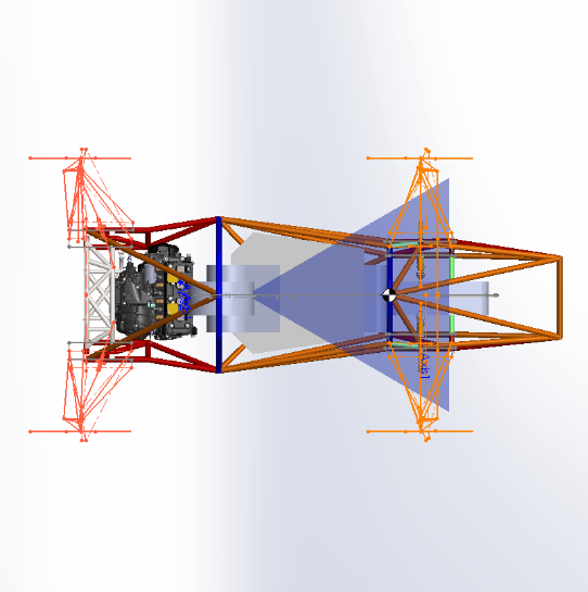
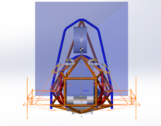
Here is the final geometry: